
Home › Products › Laminated Flexible Busbar
Laminated Flexible Busbar for Battery Modules and Power Conversion
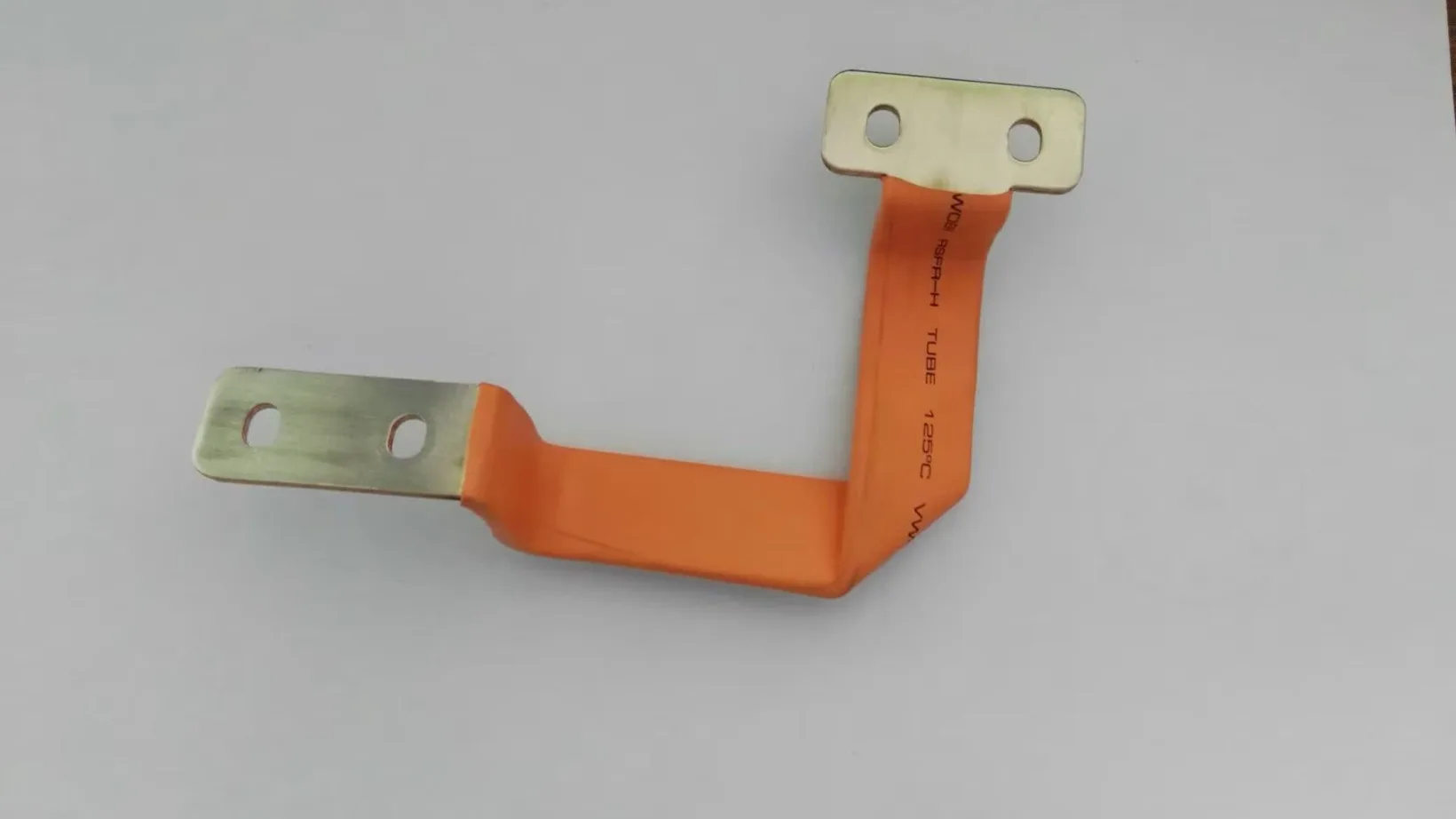
A laminated flexible busbar is a stack of thin copper foils, welded at both ends and insulated with PVC dip coating or epoxy powder, that carries high current between cells, modules, inverters and contactors. The lamination lets it absorb vibration and assembly tolerance where a rigid busbar would crack.
What is a laminated flexible busbar?
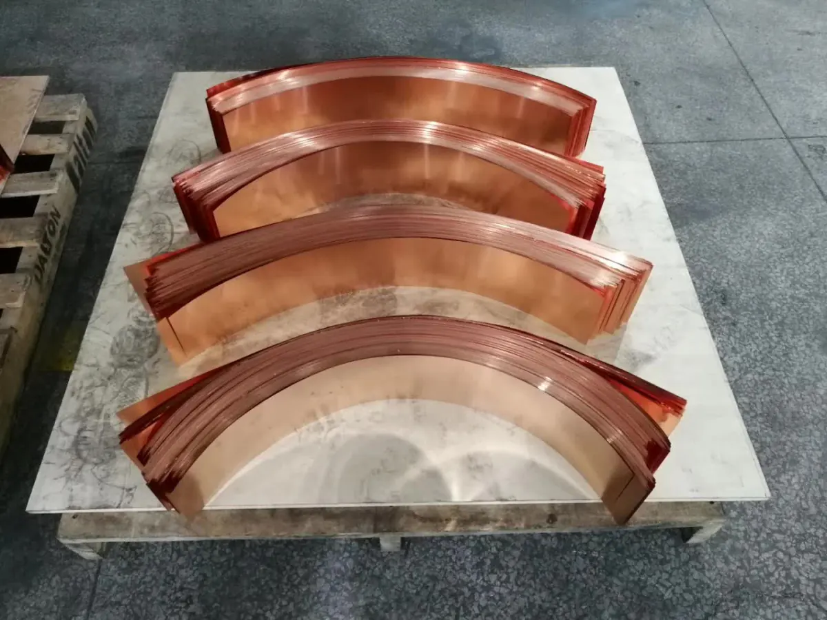
The conductor is not one solid bar. It is a stack of copper foils, each a few tenths of a millimeter thick, compressed and welded only at the two contact pads. Between those pads the foils slide against each other, so the assembly bends without work-hardening the way a solid bar does. That single property is why it appears wherever a high-current path has to cross a joint that moves: between battery modules, from a module to a busbar plate, or from an inverter to an e-drive.
Copper is chosen over aluminum in most battery applications for conductivity and joint stability under thermal cycling. Typical stock is T2 / C11000 ETP copper at 100% IACS or better. The finished part is then insulated, because inside a pack the clearance between a live conductor and the enclosure is measured in millimeters.
Laminated, braided or rigid: which one to specify
| Type | Flexibility | Current density | Typical use | Trade-off |
|---|---|---|---|---|
| Laminated flexible | High, predictable bend radius | High | Module-to-module, inverter to e-drive | Tooling cost above braided at very low volume |
| Braided | Very high, omnidirectional | Medium | Grounding straps, high-vibration joints | Larger cross-section for the same rating |
| Rigid | None | Highest | Fixed power distribution inside a pack | No tolerance absorption; stress goes into the joint |
A useful rule when reviewing a layout: if the two ends of the connection can move relative to each other during assembly, transport or thermal cycling, a rigid bar will transfer that movement into the bolted joint. Laminated flexible busbars absorb it instead.
Choosing the insulation
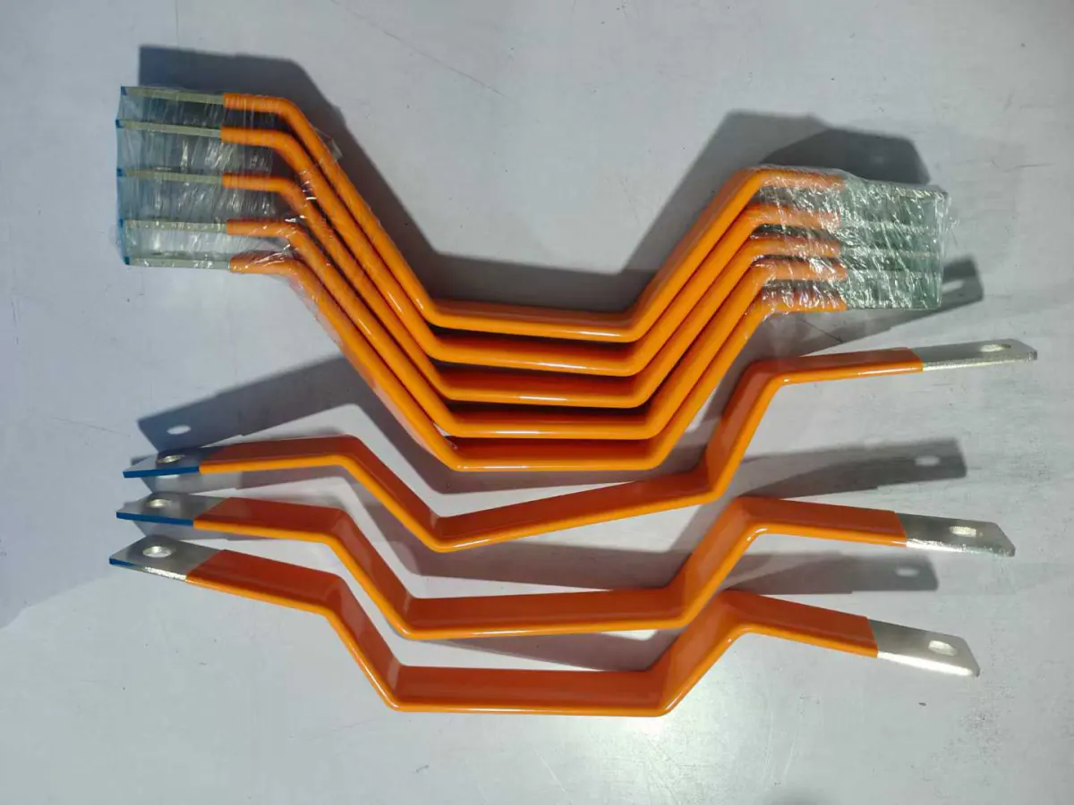
Three questions settle it for a flexible part. Will it meet moisture, salt or rough handling on the line? Does it have to fit a defined envelope? And how hot does the surrounding equipment run? Answer those and the process picks itself, because each one trades thickness against dielectric strength and temperature differently.
We run dip and powder lines in house, and heat-shrink tubing for prototypes. Thickness ranges, temperature limits and the design rules for each are set out on the dip coating page and the powder coating page. Send the withstand voltage and the operating temperature with the drawing and we will confirm the choice rather than leave it with you.
Current rating and temperature rise
A busbar is sized by the temperature rise it produces, not by a current number on its own. The same part rated for a given current in free air will run considerably hotter inside a sealed pack, and the insulation, not the copper, is usually what sets the ceiling. Tell us the ambient temperature and whether the part sits in still air, and the rating becomes a real number rather than a catalog figure.
| Installation | Typical current density | Note |
|---|---|---|
| Free air, unenclosed | 3 to 5 A/mm² | Convection available on all faces |
| Inside a sealed enclosure | Derate 30 to 50% | Depends on internal air volume |
| Bundled or stacked | Derate further | Adjacent bars heat each other |
IEC 61439-1 sets the ceiling for accessible busbars at a 70 K rise over a 35 °C ambient. In a battery pack the practical limit is usually lower, because the insulation gives out before the copper does: PVC is commonly rated to 105 °C and heat-shrink tubing to 125 °C. Send us the continuous current, the ambient and the enclosure, and we will size the cross-section against the insulation limit rather than against the copper.
Copper grade, plating and contact surfaces
The contact pads decide the long-term resistance of the joint, so they are plated. Tin is the default: low cost, solderable, stable against the aluminum and steel it will be bolted to. Nickel is specified where the joint runs hot or where the part will be laser welded to a cell terminal, because it resists diffusion better than tin at elevated temperature. Silver is used where contact resistance has to be as low as physically possible and cost is secondary.
Plating thickness, pad flatness and hole position all carry tolerances. Send them. A busbar that meets its electrical spec but misses a hole pattern by half a millimeter is scrap on the assembly line.
Bend radius, tolerance and vibration performance
Minimum bend radius is a function of stack thickness and foil count. Bending tighter than the rated radius does not fail immediately; it thins the outer foils and shortens fatigue life, which shows up months later as an intermittent connection. In automotive work the failure mode to watch is the weld at the transition from stack to pad, not the flexible section itself.
Safety requirements for the surrounding system are set out in ISO 6469-1 electrical safety for road vehicles and in IEC 62619 safety requirements for industrial secondary cells and batteries.
Where laminated flexible busbars are used
Battery packs are the largest application, connecting cells and modules where the pack frame and the module stack expand at different rates. Energy storage cabinets use the same parts at larger cross-sections. In power conversion equipment they link inverter stages, contactors and fuses. Where the connection also has to carry voltage and temperature sensing back to the BMS, the busbar is usually integrated into a CCS integrated busbar assemblies rather than supplied loose.
Insulation performance and how it is verified
Insulation is where most busbar failures start. The figures below are what these coatings typically deliver and the methods used to confirm them. Results for your part, at your coating thickness, are issued with the first article.
Salt spray resistance
Corrosion resistance is checked by neutral salt spray to ISO 9227 salt spray test method, 5% sodium chloride at 35 °C. Chinese GB/T 10125 adopts the same NSS conditions, so a report issued under either standard is directly comparable. Automotive programs commonly ask for 480 to 720 hours with no blistering or coating loss. On a flexible part the film thickness at the bend matters more than the nominal build, because that is where it thins.
Dielectric strength
Electric strength is measured to IEC 60243-1, the short-time power-frequency method, or to its identical Chinese equivalent GB/T 1408.1. Material figures in kV per millimeter do not transfer to a finished part, because field concentrates at the thinnest point rather than the average. What matters is the withstand test: battery pack programs typically specify 2.5 to 5 kV held for 60 seconds without breakdown, set by the system voltage. Ask for the value your application needs and we will confirm the build that reaches it.
Coating adhesion
Adhesion is graded by the cross-cut test in ISO 2409, adopted identically as GB/T 9286. Cut spacing follows coating thickness: 1 mm below 60 µm, 2 mm from 60 to 120 µm, 3 mm above that. The result is a class from 0 to 5 rather than a percentage, where 0 is best. Industrial coatings are normally accepted at Class 0 or Class 1.
Equipment, sampling plan and the full inspection sequence are described on our busbar testing and inspection page.
From your CAD drawing to first article
Send a 2D drawing or a 3D model. We review it for manufacturability first (bend radius against stack thickness, pad size against current, insulation clearance at the cut edges) and come back with questions before quoting rather than after. Tooling for a new profile is built in house, which is what keeps the first-article lead time predictable.
Lead time from approved drawing to first article is 3 to 7 working days where the profile runs on existing tooling, and 10 to 20 working days where a new bending or stamping tool has to be cut. Add 2 to 4 working days if the part is insulated.
Volumes from prototype through series production are handled on the same line. Details of materials, processes and capacity are on the custom busbar manufacturing service page.
Frequently asked questions
- Are you a busbar manufacturer or a trading company?
- We are a manufacturer. Stamping, bending, welding, plating and both insulation lines are in our own plant in China, which is where quotations, tooling and inspection reports come from. Factory visits are welcome by appointment.
- What is the difference between a laminated and a braided flexible busbar?
- A laminated busbar is built from flat foils and bends mainly in one plane, with a defined minimum radius and higher current density for a given cross-section. A braid is woven from round strands, flexes in any direction, and tolerates more movement, but needs a larger cross-section for the same rating. Choose laminated for compact, repeatable module connections; choose braid for grounding straps and joints that move unpredictably.
- Which insulation should a flexible busbar use?
- Start from the environment and the envelope. A dipped film is thicker and more forgiving of handling; a powder film is thinner and holds tighter dimensions. On a flexible part there is a third factor the process pages cover in detail: how the film behaves at the bend, where it is always thinnest.
- What are the disadvantages of flexible busbars?
- Three, honestly. Current density is lower than a solid bar of the same outline, so a flexible part is physically larger for the same rating. Unit cost is higher, because the stack has to be welded and insulated rather than simply cut and punched. And the flexible section has a fatigue limit. Bend it tighter than its rated radius, or cycle it beyond the design count, and the failure appears at the weld transition rather than in the middle. Where nothing moves, a rigid bar is the better engineering answer.
- How do I know if a busbar is sized correctly?
- Measure temperature rise under the real load, in the real enclosure, at the real ambient. A part that runs within its insulation temperature limit under worst-case conditions is sized correctly; one that is close to the limit in a lab at room temperature is not. Watch the joints rather than the middle of the bar. A loose or oxidized contact shows up as a local hot spot long before the conductor itself is in trouble.
- What drawing formats do you accept?
- DWG, DXF, PDF for 2D; STEP or IGES for 3D. A dimensioned PDF alone is enough to start a quotation.
- Can you supply prototypes as well as production quantities?
- Yes. Prototypes and series parts run on the same equipment, so a validated sample transfers to production without a process change.
Request a quote
Send the drawing, the continuous current, the ambient temperature and the installation condition, and we will come back with a manufacturability review and a price. Start an RFQ.