
Home › Products › CCS Integrated Busbar
CCS Integrated Busbar: What Goes Into a Cell Contacting System
A CCS integrated busbar, or cell contacting system, is a single assembly that carries the main current between cells and routes each cell group’s voltage and temperature signals back to the BMS. Copper busbars, a signal acquisition layer and a plastic carrier are joined into one part that drops onto the cell stack in a single operation.
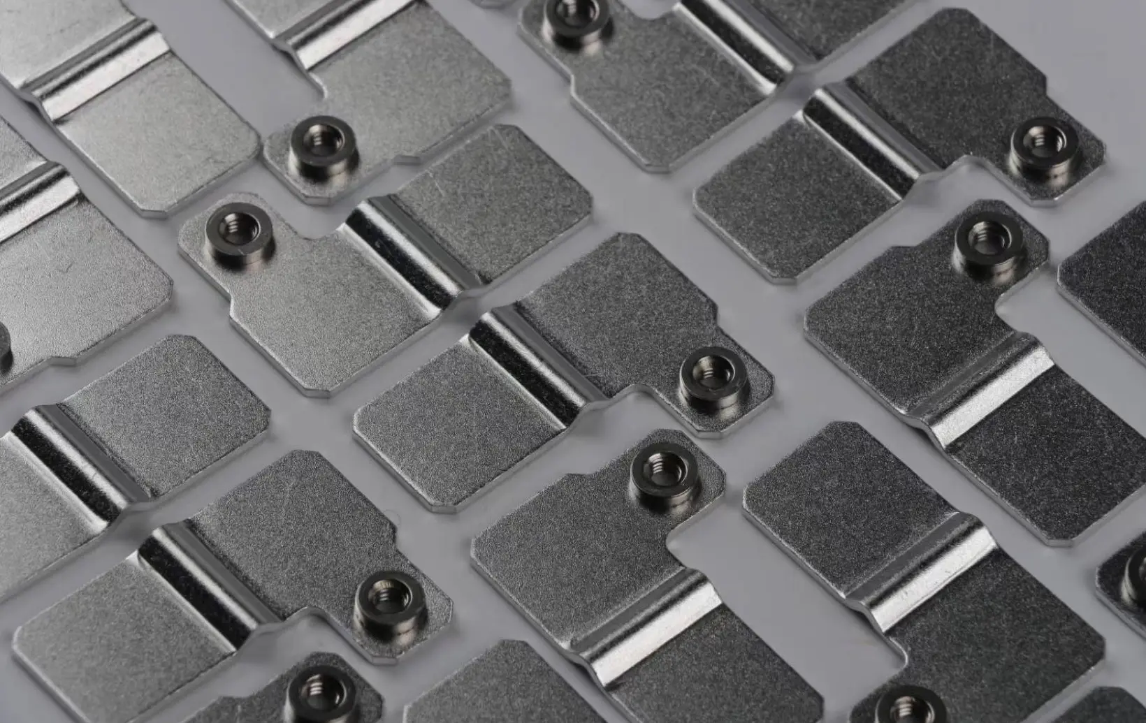
What a CCS replaces
Before integration, a module needed separate busbars, a wire harness, temperature sensors and a set of fasteners, each installed and inspected on its own. A CCS collapses that into one part. The assembly line places it once, welds it once and tests it once, which is why the approach took over as pack volumes rose.
The gain is not only labor. Every connector and crimp removed is a joint that can no longer loosen, corrode or read a wrong voltage. Fewer discrete parts also means the module height and the internal clearances become predictable, because they are set by one molded carrier rather than by how a harness happened to be routed.
What goes into one
| Layer | Function | Typical construction |
|---|---|---|
| Busbars | Carry the main current between cells | Copper or aluminum, stamped and plated |
| Signal acquisition | Route cell voltage and temperature to the BMS | FPC, FFC, PCB or wire harness |
| Carrier | Locate everything and insulate between layers | Injection molded plastic frame |
| Sensors | Report module temperature | NTC placed against the busbar or cell |
| Protection | Open the path on overcurrent | Fusible link built into the busbar |
Choosing the signal acquisition layer
This is the decision that shapes cost, thickness and lead time, and it is worth making early rather than at tooling release.
FPC is the flexible printed circuit, the thinnest option, and the usual choice for high volume automotive modules where module height is tight. Tooling cost is real, so it suits a stable design rather than a program still moving.
FFC is the flat flexible cable, cheaper than FPC and simpler to change, appropriate where the sense points sit in a straightforward line and the design may still evolve.
PCB is rigid, carries components if the module needs any local circuitry, and handles larger current on the sense side. It is thicker and less tolerant of vibration than a flexible layer.
Wire harness is the traditional route. It is still the right answer for low volume, for prototypes, and for energy storage modules where module height is not the constraint it is in a vehicle.
The busbar side
This is the layer we make, and it is where most of the electrical risk sits. Copper thickness follows the cell group current rather than a standard gauge. Plating follows the joining method: nickel where the busbar will be laser welded to a cell terminal, because it resists diffusion at elevated temperature better than tin, and tin where the joint is bolted.
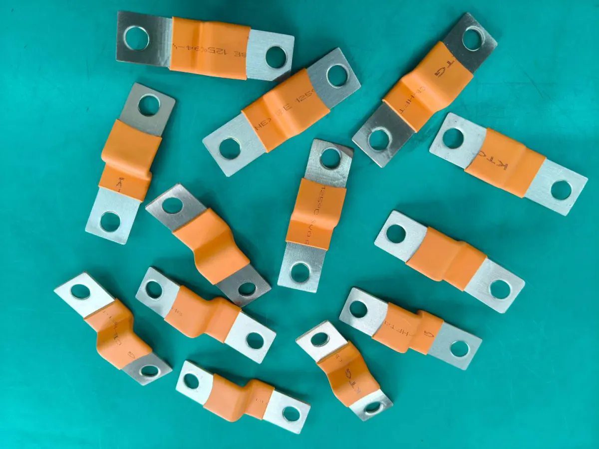
Where the cell stack and the carrier expand at different rates, a rigid busbar transfers that movement straight into the weld. Compliance is designed in instead, either as a formed relief in the bar or as a flexible section. The same reasoning behind laminated flexible busbars for battery modules applies inside a CCS, at a smaller scale.
Fusible links are cut into the busbar where the design calls for cell-level protection. The link geometry sets the trip characteristic, so it is a drawing dimension with a tolerance, not a feature to be left to the toolmaker.
Joining the busbar to the cell terminal
The weld between busbar and cell terminal is the joint that carries the full cell group current, and the one the module cannot be repaired at. Three methods are in common use, and each drives a different requirement back onto the busbar.
Laser welding is the volume method. It is fast, non-contact and puts very little heat into the cell, which matters because a cell terminal is millimeters from electrolyte. It also demands a tight and repeatable gap between busbar and terminal, which is why CCS flatness is a controlled dimension rather than a cosmetic one. Nickel plating is normally specified over tin here, because tin can diffuse into the weld pool and leave a brittle joint.
Ultrasonic welding joins by friction rather than melting, so it suits dissimilar metals such as an aluminum terminal against a copper busbar. It needs access for the sonotrode from one side and a solid anvil from the other, which constrains where the carrier can place ribs.
Resistance welding remains common on cylindrical cells with a thin busbar or a welded tab, and is the least demanding on equipment. It puts more heat into the cell than a laser does, so busbar thickness at the weld area is usually reduced locally.
Tell us the joining method before the busbar thickness and plating are fixed. Changing it afterwards usually means re-cutting the tool, because the weld area geometry is part of the stamping rather than a secondary operation.
Where the busbar layer needs insulating away from the weld zones, the same processes used on standalone bars apply, and the masking rules are the same as on the epoxy powder coated busbar insulation page.
How the layers are joined
Two methods dominate. Hot pressing bonds the busbars and the signal layer to the carrier under heat and pressure, giving a flat assembly with no added hardware. Riveting is mechanical, more tolerant of rework, and preferred where a layer may need to be replaced during a program.
Whichever is used, the assembly then has to sit flat. A CCS that bows by a millimeter will not present every busbar to its cell terminal at the same height, and the welds at the high corner will be the ones that fail in service rather than at end-of-line test.
What we need to quote
A CCS is quoted from the module layout, not from a part description. The inputs that matter: cell format and arrangement, series and parallel configuration, continuous and peak current per cell group, the sense point map, the joining method to the cell terminals, module height available, and whether fusible links are required. Send the module drawing and we will come back with questions before quoting.
Lead time from approved drawing to first article is longer than for a plain busbar, because the carrier needs its own tool. Materials, processes and capacity are on the our manufacturing processes and capacity page.
Testing and verification
Insulation between the busbar layer and the carrier is checked by withstand voltage. Contact resistance is measured across each busbar. Continuity and pin mapping on the signal layer are tested against the sense point map, because a CCS that is electrically sound but reads cell voltages in the wrong order is worse than one that fails outright. Environmental testing follows the same methods described on how assemblies are verified before shipment page.
Safety requirements for the surrounding system are set out in IEC 62619 safety requirements for industrial secondary cells and in ISO 6469-1 electrical safety for road vehicles. Stationary storage programs increasingly ask for evidence against the UL 9540A test method.
Frequently asked questions
- Are you a busbar manufacturer or a trading company?
- A manufacturer. The busbar layer of every CCS we ship is stamped, formed and plated on our own equipment in Foshan, China, and the assembly is integrated here rather than bought in finished. You can see the line before placing an order; visits are arranged by appointment.
- What is the difference between CCS and CCU?
- Nothing substantial. Cell contacting system, cell contacting unit and cell connection system describe the same assembly. Different pack makers use different names, and specifications often mix them within one document.
- Should I specify FPC or FFC?
- FPC where module height is tight and the design is frozen, because the tooling investment pays back over volume. FFC where the sense points run in a simple line, the program may still change, or the volume does not justify FPC tooling.
- Can a CCS include fusible links?
- Yes. The links are cut into the busbar itself, and the geometry sets the trip characteristic. Give us the required current rating rather than a link width, and mark it as a controlled dimension on the drawing.
- Do you supply the FPC and the plastic carrier as well?
- The busbar layer is made in house. The signal layer and the molded carrier are sourced to your specification and integrated here, so you receive one assembly with one part number rather than three deliveries to coordinate.
- Can you build prototypes before tooling is released?
- Yes. Prototype CCS assemblies are usually built with a wire harness or FFC signal layer, which avoids committing to FPC tooling before the sense point map is settled.
Request a quote
Send the module layout, the series and parallel configuration, the current per cell group and the sense point map. Start an RFQ.